How to build Small & Mid Power RF Attenuators & RF Loads.
Attenuators
RF attenuators are very usefull devises in order to protect VNA’s Spectrum Analyzes, Bench Wattmeters & Frequency Meters
For each purpose we can use attenuators to decrease the output Power of a DUT from the physical level to a lower one which can be measured
with safety without causing damage to our sensitive Laboratory measurement equipement. Mid & High Power Attenuator usally made of a High Power Thin Film Resistor which contains Tantalum Nitride & the dangerous BeO for low thermal contact resistance. Usally it’s a Pi or T Network printed on the material as a solid state device with input & output terminals.
The common RF Attenuator has the same input output Z which is 50 Ohm. For special designs the manufactures can produce different custom Z inputs/outputs.
It could be used as a Dummy Load too but you need to connect a 50ohm Resistor Load terminator with suitable power ratings to the output terminal of the attenuator.

Calculate an attenuator to fit your needs.
You need to know the following parametres
1. Maximum Power Rated & Cooling.
What is the maximum Rated Power for measurement?
Never use a 50W attenuator f.e. to measure a 50W DUT (Device Under Test), you need a bigger attenuator to avoid possible damage the attenuator or your device or both.
You have to avoid two critical mistakes if you are using a 50w attenuator for a DUT with 50W output, you can damage the attenuator & burn the resistor,
or maybe the attenuator can be shorted or decrease the resistance between the input – output & it will destroy the DUT or the Instrument or both of them!
As about the max power for an attenuator in practice you cannot reach the max power level about 100% without a great risk.
First you have to take a look at manufacture’s datasheet, you can see into the session Safe Operation Area the maximum working temperature typically (100C) for 100% Power Use.
That means a very well calculated heatsink with blister copper plate build in or extra added with possible extra cooling fan & very special Thermal Paste with Low Thermal Resistance <0.010C-in²/W must be used.

2. Attenuation.
Most Solid State Chip Attenuator Series have a various range of attenuation for every use starting from 1db to 40db, with common range 1,2,3,4,5,8,10,12,15,20,25,30,35,40db.
You can easily find power chips starting from 0.5W to 1KW.
If you need more attenuation than 40db you can use in series attenuators to reach the desired level.
F.e if you like an attenuation 44db you can use in series a 40db + 4db attenuator.
I suggest you to void a 30db + 10db + 1db + 3db in series network which can decrease the measurement accuracy & it can increase the measurement error too.
Each attenuator has RF connectors for IN/OUT terminals, each connector can add an attenuation (loss) to the total network value which is really unwanted.
You can easily calculate this f.e. at the normalize proceedure on the instrument & you can remove it from the final measurements but it’s always an additional unwanted task to do.
The best way to choose an attenuator is to find your measurement’s device max power input limit, the best way is to read manufacture’s specifications.
always the manufacture noticed the maximum input level & believe me you don’t need to reach or exceed it.
F.e. the Rigol DSA815 needs max +20dbm Input signal more can serious damage the analyzer, that means maximum input power 100mw.
Well you don’t need to reach this level to learn if it’s safe or not, usally the maximum level is more than the recommended but you don’t want to proof it.
3. Frequency Range.
what is the frequency range of the DUT you need to measure, or what range you need to cover for future use?
Most of these attenuators can cover measurement from DC to 20Ghz or more, it depens from the power, manufacture & price of course!
4. Mobility, you need it for your lab or for field measurements?
That means you have to compromise between the weight & the size for a wanted attenuator.
Small power is not a problem you can built it too small & you can install it directly at the instrument output,
Medium power you have to built it seperate & you need to install it between devices with cables.
High Power it’s a really heavy attenuator not easy to carry without a carrying case with wheels or a strong guy to carry the equipment for you!
When I was started to built the following attenuators it was about a very importand project for Geophysical analalysis.
Low Power Attenuators.
There are several serious manufactures they build high quality & presicion attenuators for low power input.
My favorite is MiniCiruits & specially the PAT Series Attenuators PAT-10+, PAT-20+, PAT-30+ etc.
A chip resistor attenuator with low power ratings 1W with frequecncy range DC to 7Ghz.
You can easily build a special PCB f.e. Rogers & you can install it into two BNC or SMA Male Female Connectors.
Here are a few fotos with the construction procedure & the measurements for these goodies.

Full Assembled Attenuators 10, 20 , 30DB

PCB Assembled With BNC Main Bodies

BNC Back Nuts & PCB Installed

PAT-XX+ Factory Package

Dissasembled BNC Male/Female

Spectrum Analysis For A 10 DB Attenuator
You can Dowload The PCB Here PAT-XX+ 23.6mm7.4mm
Medium Power Attenuators
If you decide to build a Medium Power Attenuator you need to calculate the cooling part (heatsink).
Also you need to buy a high grade recommended thermal paste for this.
I’m using a very special paste which is an experimental lab product not easy to produce & find to the market
with Thermal impedance (Resistance) 0.009 C-Sq-In/W
but i suggest you to use the PK-3 Paste by www.proclimatech.com which it’s suitable with the following specifications:
Specific Gravity 2.7gr/sq-cm
Adhesiveness 330000 Cps
Thermal Conductivity 11.2 W/m-C
Thermal impedance (Resistance) 0.013 C-Sq-In/W

http://www.prolimatech.com/en/products/detail.asp?id=1582
For this project i decide to use a 100W attenuator Flange Resistor By AVX Type RP10975A30DBFPBK 30DB Attenuation (attenuator’s for max input 100W the output is about 100mw) With frequency range from DC to 3gHz.
Also an enclosure metal Box GAINTA BS35 to fit the connectors & to keep the resistor safe from dust, moisture & unwanted electromagnetic propagation.
An excellent heatsink from an old HP Desktop PC with copper base were used (Heatsink Type HP P/N:409302-001) which can handle without air cooling 100W
but it’s not recommended, it’s necessary to install a fan on the heatsink for 24/24h use.
Connectors N-TYPE For the input & BNC or SMA for the output, here I’m using BNC without problems.
Here are a few photos with the construction procedure & the measurements for these goodies.

GUIDA BOX BS35 With Installed Connectors
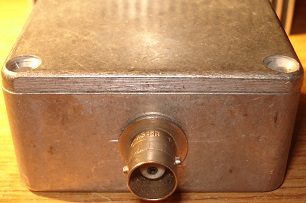
GUIDA BOX BS35 BNC Overview

Chip Attenuator Into The Box & Heatsink Included

GUIDA BOX BS35 Drilled To Fit Onto Heatsink

HP P/N:409302-001 Heatsink Front View

HP P/N:409302-001 Heatsink Right View

HP P/N:409302-001 Heatsink Bottom View

Attenuator Full Assembled

Spectrum Analysis For A 30 DB Attenuator Which Is Finally 28DBBut It’s OK!
Here is a medium power 30db Flange attenuator 500W By RFLabs build in a GAINTA BS35 box too but with a large heatsink with extra cooper plate 10mm installed on the Al.
The project also contains a 50Ohm Dummy Load 800W power ratings from DC to 1.5Ghz.

Heatsink KL288 400mm * 200mm

Cooper Plate 400*200*10mm

RFLABS 500W Attenuator at the left side & LOAD Resistor 800W At The Centre.

Full Assembled Sealed Into The Boxes Under Test

Attenutor 500W Spectrum Analysis
Regards
AkisT

Recent Comments