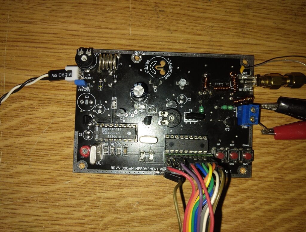
That’s it, an old PLL came from 90’s! If you search this you can find several versions working or not with errors, mistakes even bad hex files. This is an upgraded SMD version of the original prototype, most of all the electrolytic capacitors have been replaced with SMD Tantalium type, all the other capacitors are C0G type, finally all the resistors are SMD 1% tolerance 1/2W. Regarding output filter part a few critical changes were made, without any changes the output power increased dramatically starting about 24dBm (251.2mW) from 87Mhz ending to 21.5dBm (141.3mW) up to 108Mhz. After changes were made the power at the lower frequency of 87Mhz was 24.20dBm (263.0mW) at 97.5Mhz 24.02dBm (252.3mW) and up to 108Mhz 23.24dBm (210.9mW). Measurements of total harmonic distortion were accepted THD about 0.28@97.5Mhz, -62.23@195Mhz, -63.21dBm@292.5Mhz, -62.59@390Mhz etc…
The quality of sound is quite enough but the audio level is lower than expected. Tested with MPX signal the quality is acceptable.
More Measurements And Ideas…Coming Soon…Please Stay Tuned!
Best Regards AkisT

That was an old project, a high quality digital upgrade for the classic BIRD 43 Model. The new upgrade is a completed data acquisition system with basic VSWR, SWR, Wf, Wr and extra calculation benefits such Ndb, dbm, Φ, p.


It’s also can support overscalling and Wr limitation alarm, it can support optional SD card reader and PC connection via USB. Powered with built-in 2000mah high-quality li-on battery, which can last for 45 hours on a full charge, and can be used while charging like a phone.

The prototype Bezel was printed by 3d printer and it will be available as soon as possible.
This project is in test progress and it’s not available at the moment.


This is a highly recommended upgrade version of the originally existed hardware motor controller unit for the earlier version of Super Achille Model ROV. High grade 2Oz Black Matt PCB, all the parts were replaced with high quality materials, the pcb was kept at the original dimensions, drastic updates – improvements for protection and maintenance purposes were made.
Triggered by the specific request of Kostas Thoktarides – Planet Blue.

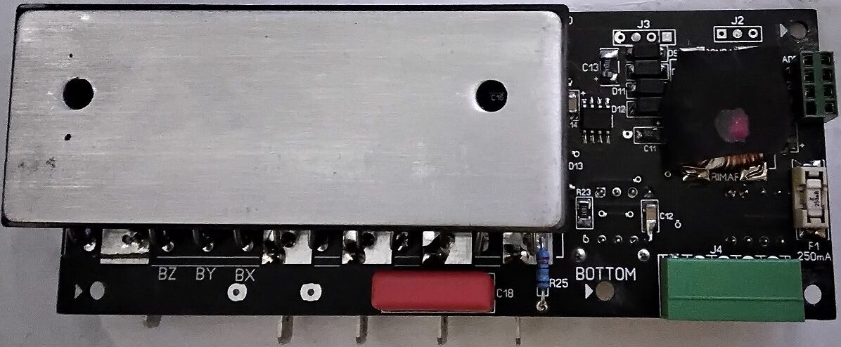

This is a highly recommended upgrade version of the originally existed hardware motor controller unit for the latest version of Super Achille Model ROV. High grade 2Oz Black Matt PCB, all the parts were replaced with high quality materials, the pcb was kept at the original dimensions, drastic updates – improvements for protection and maintenance purposes were made.
Triggered by the specific request of Kostas Thoktarides – Planet Blue.


This Is The Announcement Of New Enterprice 2020 Version Of Scientific Pre-seismic Electric Signal Data Acquisition System almost finished prototype, A Crisistech Labs Innovated Design. An Extremly Powerful, Small Device From Factor, Very Low Consuption Less Than 4.5W, Compact Design, Weight Less Than 1Kgr ,A High Grade Intergraded Accurate Measurement Device, Can Support 24/24hrs Pre-seismic Electrical Signal Recordings In Fully Customized Offsets, Variable Sampling Rate, Can Also Support Access Through Modern Telemetry Of The Recorded Data From Anywhere.


A simple PSU Automation design for single output power supplies Up To 50V/10A DC Output.
Specifications:
In/Out Capasitance Filter 20.000uF/63V.
Output: Dual AC PSU 2 x 9v 3.6VA For Digital Panel Meters (XH2.54-4P 4 poles Connector).
Thermal Protection 2 x Thermal Switches Inputs, with LED indicator (KF2510-2P 2 poles Connector).
Thermal Speed Controlled Fan 4 x 12V Outputs 200mA max consumption (KF2510-3P 3 poles Connector).
Thermal Protection With NTC Thermistors Dual Input (KF2510-2P 2 poles Connector).
Fuse Breaker Led Alarm Indicator (XH2.54 2 poles Connector), External Chassis Fuse Holder Needed (Wafer Connector 3.96mm 2 poles).
Main Transformer Input (Wafer Connector 3.96mm 2 poles) and Cut Off Protection Circuit via Relay.
AC Input 220V 10A Max (Wafer Connector 3.96mm 3 poles).
Dimensions: W 100mm x L 100mm x H 50mm
Weight: 530gr
Schematics, Gerbers And BOM List Are Available
This project is for sale, available for manufactures only.
For technical – hardware and purchase inquiries contact at : akis@crisistech.com
Regards
AkisT
This is a highly upgraded version of the originally hardware presented (2007) by Thanassoulas, C. (B.Sc in Physics, M.Sc – Ph.D in Applied Geophysics) in the monograph “Short-term Earthquake Prediction (2007)” and in: Link
Triggered by the specific request, of a seismogenic country University, to supply them with a number of complete hardware units, a drastic update, with the cutting edge today’s electronic technology, of the original prototype was utilized by Crisistech Labs. The new hardware is an “All in One” unit presented in the following Fotos


Datasheets Downloadable Versions
Short Brosure Download
Detailed Brosure Download
For further scientific inquiries contact Dr. Thanassoulas, C. at : thandin@otenet.gr
For technical – hardware and purchase inquiries contact at : akis@crisistech.com

Crisistech Brand Name Was Born On May 2007 Before Greek Crisis, The Domain Name & The Site Was Created On 2011-07-22.
Our Philosophy 10 Letters 10 Words…Crisistech
C-reation
R-ecommendation
I-nspiration
S-amplification
I-nnovation
S-ofistication
T-echnological
E-volution
C-oordination
H-elp
There Was Our First Try To Share – Insert Technology, Innovation, Inspiration & Sharing Ideas Into The Real Word.
 WARNING THESE MODIFICATIONS ARE EXTREMLY DANGEROUS FOR PEOPLE WITH LOW EXPERIENCE TO SMPS HIGH VOLTAGE CIRCUITS. DO NOT ATTEMP THESE MODIFICATIONS IF YOU ARE NOT AN ELECTRONIC ENGINEER OR AUTHORIZED TECHNICIAN ELECTRICITY CAN HARM YOURSELF PERMANENTY, IT CAN CAUSE DISABILITY OR DEATH. I’M NOT RESPONSIBLE OR I HAVE NOTHING TO DO WITH YOUR ACTIONS. IF YOU DON’T UNDERSTAND PLEASE LEAVE THIS PAGE IMMEDIATELY. There Was An Emergency Task To Build A 12V 180A Power Supply But there was a deadline & I couldn’t Design It From The Beggining Spending Days & Weeks For A Single Lab Unit, So I decide To Use My Experience In SMPS Reverse Engineering. The First High Power SMPS I Was Found A HP PS3701-1 Spare Part Number 365063-001 From An Old ML350 Server Looks A Great Choise. The Reason Is Too Simple, All This Units Designed To Work In Parallel Mode Into HP Servers, So For Parallel Use I Had To Worried About The Lenght & The Diameter Of The Cabling Inside the Enclosure & Finally I Need To Use The Same Lenght Of Cables If I Had To Parallel More Than One Units.
  Specifications 1. Input 100-240VAC 2. Output Main Output +12V/60A, A Small Negative -12V/0.5a, & An Auxiliary Output +5V/1A First Of All I Had To Check My Memory About These PSU’s, Are Well Protected Against Short Circuit & Reverse Polarity? Yes!!! It Was Absolutely True. Each Of These Units Can Be Used In Series & Parallel Mode With A Few Modifications BUT NEVER TRY TO DO IT IF YOU ARE NOT A AUTHORIZED TECHNICIAN WITH EXPERIENCE TO HIGH POWER SMPS UNITS. There Was An Issue With The Negative Output Pole It Was Grounded & The Chassis Too But We’d Like A Grounded Chassis Anyway, So That Was Not Ideal For Serial Mode Use, It Could Be A Nightmare Trying Connect Two Units In Series Mode! I Had To Modify Each Unit Except The First One IN ANY CASE THIS ONE MUST BE GROUNDED So I Made A Decision To Teardown A Unit, But Before I Took A Few Measurements To Verify & Secure The Success Story…lol. As You Can See At The Photo There Are Four Outputs 12V At The Left & Right, But You Have To Split The Outputs Using 15 Amps Fuses To Avoid Possible Over Current Damage To Output Pads & Traces. All You Need To Know About Outputs Was Marked, See The Next Foto.
  I Had To Measure Each Output & To Take A Closer Look To The Whole PSU Design & Construction. I Noticed That The Green Status Light At The Back Side It Was Activated Only If I Had To Connect The Remote Control Switch Between The Pin RC & (-) Negative All Negative Outputs Are Located At The Left & Right Sides At The Edge You Can Connect It everywhere.
  Now I Had To Do A Careful Inspection About The Ground So I Had To Take A Closer Look At The Front Side Where Located The FAN & The Power Outputs. Aha!!! There Was An Issue There, The Enclosure Chassis Was In Contact With The Negative Outputs. I Had To Isolate This Area To Avoid A Connection Between Main Ground & Negative Output Pole For Each PSU Which Was The Second Or The Third In Series Of The Array. A Thin PVC Foil Placed With Silicon Glue To Isolate The Area As You Can See At The Next Foto
  After This I Had To Teardown The PSU To Continue The Mods! Take A Look After Removing The One Piece Of Enclosure.
 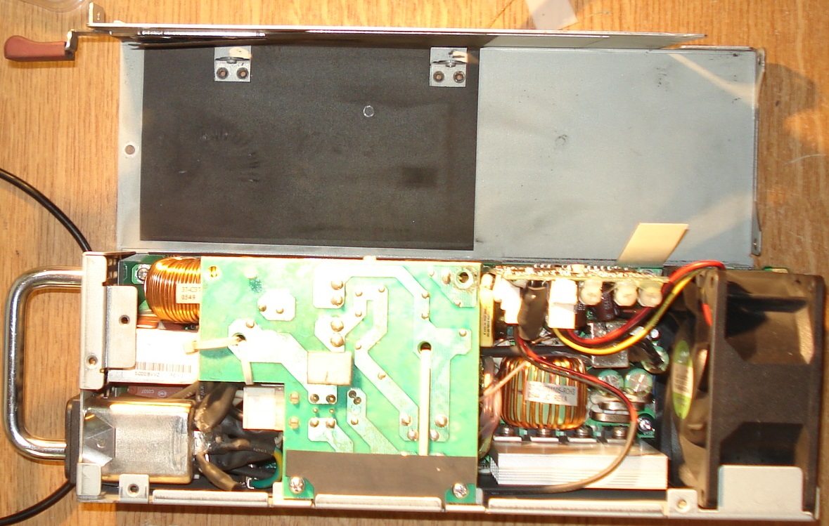 The First Thing I Had To Do Was To Remove The Ground Connection Between The Chassis & The Negative PCB Output Which Located Beside The Small Vertical Control Board. It Was Very Easy By Removing The Screw As Shown At The Next Foto
  Then I Had To Place A Small Foil Of PVC With Silicon Glue Between The Chassis Spacer & The PCB.
  DON’T PLACE THE SCREW BACK
  After This MOD I Had To Isolate The Main PSU Circuit From Earth Ground But I Had To Place A Capasitor Between Earth Ground & Main PSU Board For Ground Isolation & To Make A Path For AC Signals Between Ground & Main Board PCB. First Of All I Had To Move The Isolation Tube Sield From The Mains Plug Ground Pole. Then I Had To Remove The Yello Ground Cable From The Main’s Ground Pole
  Then I Had To Place A Capasitor Between The Cable & The Ground Pole. It Was Very Importand To Isolate Everything Included Capasitor & Cables After This Modification. A Capasitor Value of 100nf/275V AC X3 Series Or Greater Voltage It Will Be Fine.
 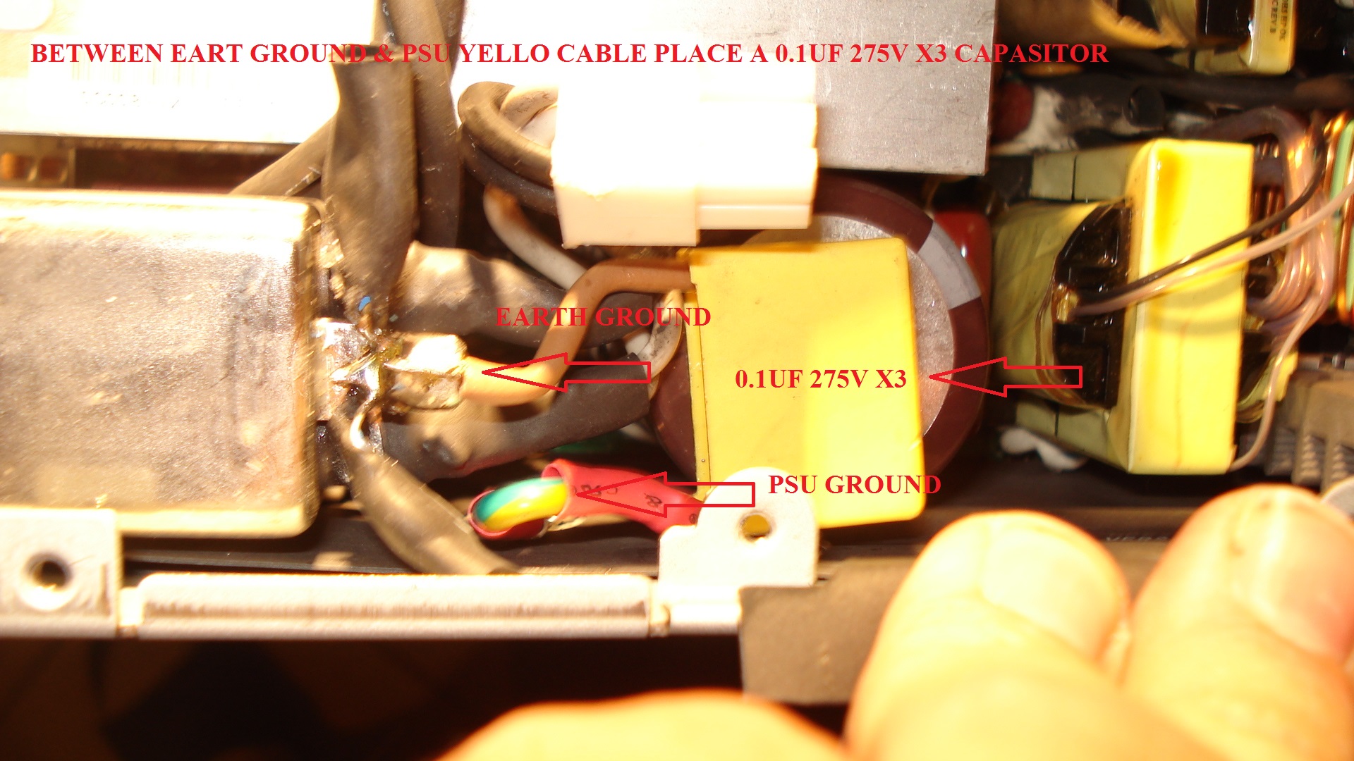 After All These Mods I Had To Close The Enclosure Back. PLEASE READ CARFEFULLY IT’S VERY IMPORTANT!!! I Had To Check About Any Unwanted Connections Between Chassis & Negative Outputs Before I Close The Enclosure. I Turn On The Switch Of The Non Grounded Second Unit & Between Ground & Negative Output Or Positive Pole Finally Was Measured At Least 110V AC!!! Next Step Was To Build An Automation Circuit & A Front Panel PCB To Protect Myself For Possible AC Leak Voltage At The Outputs When It Was In Use At The Bench. This Circuit Was An AC Signal Detector With Optical & Sound Alarm, I Think It’s Time To Explain It.
  I Had To Built 3 Of These PSU’s For Parallel & Series Use. As I Wrote Before The Second & Third Unit’s Was Floated Not Grounded So Any Possible Leak AC Voltage Can Harm Myself Or Any Connected DUT. I Had To Include A Protection Circuit For Myself & Other Users Safety, F.E. iF Someone Tries To Turn On The Second Ungrounded Unit & Working With It The Unit Will Be Floating & There It’s Quite Possible To Harm Himself Or DUT’s. So For Everyone Unsuspected Or layman Guy There Was A Back Door Directly To Death! This Issue Can Be Resolved With Warning Optical & Sound Alarm To Prevent The Possible Damage Or Failure In Case The Ground Was Missed Or Forgotten. My Suggestion Is To Read My Thoughts & Use This Device Wisely. When You Using These As Stand Alone Units. Don’t Touch The Output Or Connect A Device At The Second Or Third Unit Without Earth Ground Present At The Negative Pole Both Of These Units Please Take A Look At The Following Foto, Each Output Has It’s Own Thermal Fuse At 15A Each Unit Has 4 Outputs That Means 15mps x 4 = 60Amps. Each Unit Must Have The Same Leangh Of Cabling To Avoid Possible Port Over Load. Each Cable For Internal Cabling Is 8 AWG FOC (Free Oxygen Copper) Except The Main Negative Cable Which Is 4 AWG FOC Too.
 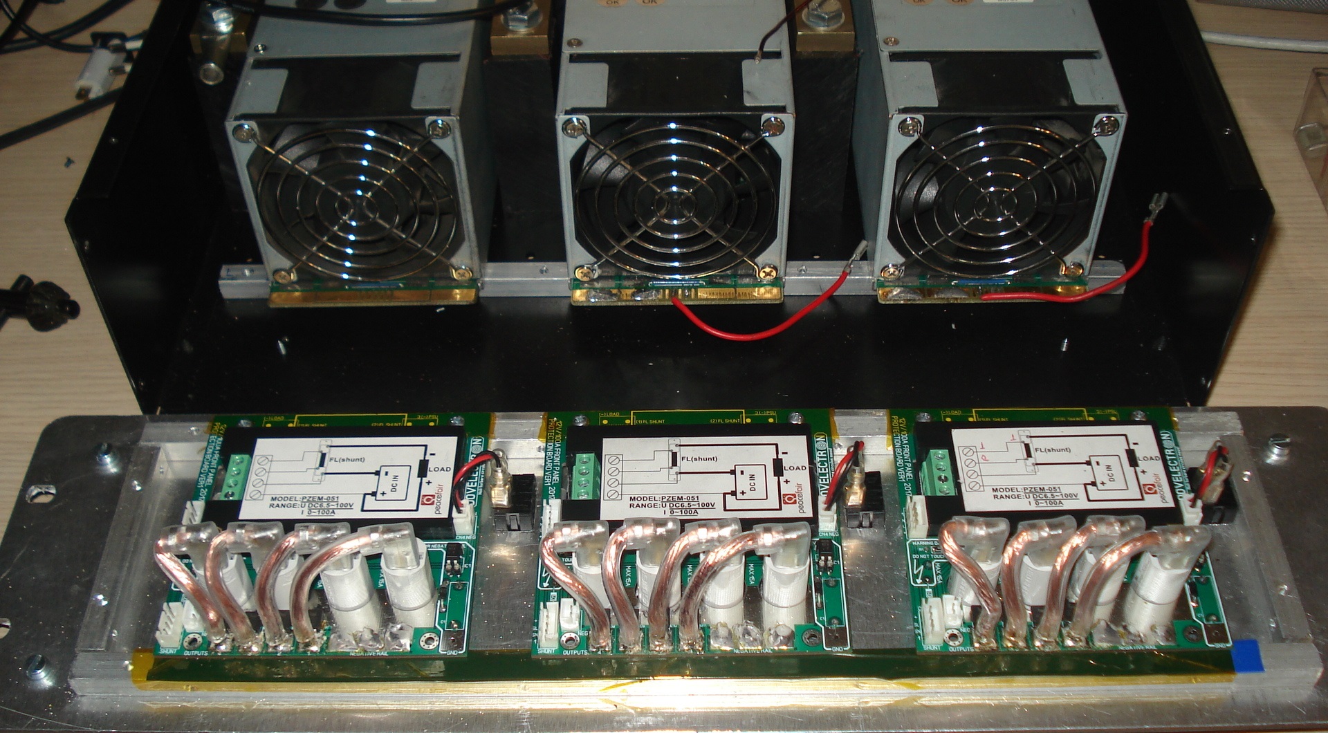 For This Project We Bought Cheap LCD Panel Meters For Voltage, Current, Power & Energy Data Logging. You Can See The Front Panel Inclunding Switches, Heavy Duty PCB Terminal Block Outputs, Panel Multi Meters, Thermal Resetable Fuses, Warning Sings Instructions & Functions. This Is The 40Amps Output Version Per Unit, The Latest One Was 60Amps Per Unit.
  Inside The Enclosure You Can See Three 100Amps Shunts One For Each PSU.
  Each Unit Has A Independent Input For Tha Main AC At The Back Side Panel.
  Suggested Connection Diagram Below There Was An Error Typing 108Amps In Parallel The Right Is 180Amps!
  Conclusions It’s Working Like A Charm! Alarms Are Working Pretty Well Too. We’ve Test It At 36V In Seies At 55Amps & It Was Perfect. We’ve Tested As 12V Stand Alone Each Unit But With Grounded For All Units The Common (-) Outputs 12V/55Amps. Finally The Great Test 12V/140Amps Rated To A Power Inverter! Kind Regards Akis T


This is a Front Panel board for most wanted RDVV PLL.


It can be used for all common versions from beggining until the 2006’s Versions.
The PCB design contains the following functions including a few older partitial designs i made many years ago for similar personal projects.
1. Analog Volume Control
2. Analog Power Control
3. RDVV LCD Main Display attached
4. Audio Peak Detector with Led
5. Analog Audio Level Meter (1991)
6. Analog PWR/SWR Meter (Only the panel meter session with the level controll but without PWR/SWR Coupler) (1987)
7. Thermal Protection for the RDVV Power Stage & For A Possible Linear Amplifier as a next power stage. (1983)
8. Tone Test Generator 1Khz (1981)
9. Mono MPX AF Input Selector.
10. Premphasis 50/75us Included + Input Selector. (1981)
11. SWR & Thermal Protection with optical & sound alarm. (1987)
Schematics, Gerbers And BOM List Are Available
This project is for sale, available for manufactures only.
For technical – hardware and purchase inquiries contact at : akis@crisistech.com

Recent Comments